

Topic Last Modified: 2011-01-25
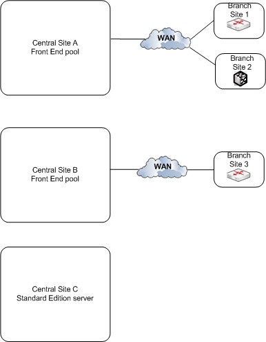
The reference topology for multiple data centers is for any size of organization with more than one central site. The exact topology in the following diagram is for an organization of 70,000 users, with 40,000 users at Central Site A and 30,000 at Central Site B. The type of topology shown in this diagram can accommodate organizations with any number of users.
This topology is shown in multiple diagrams, with an overview first followed by detailed views of the central sites.
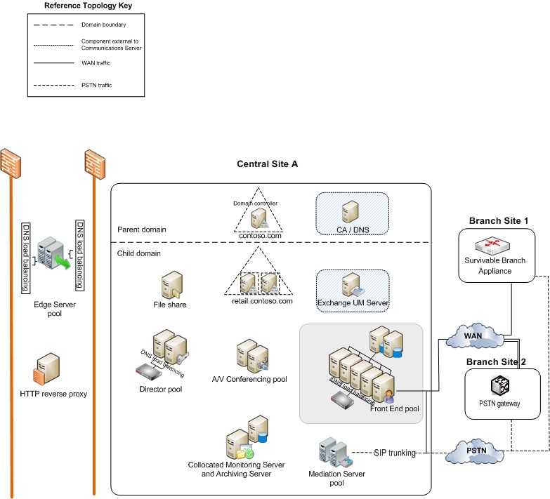
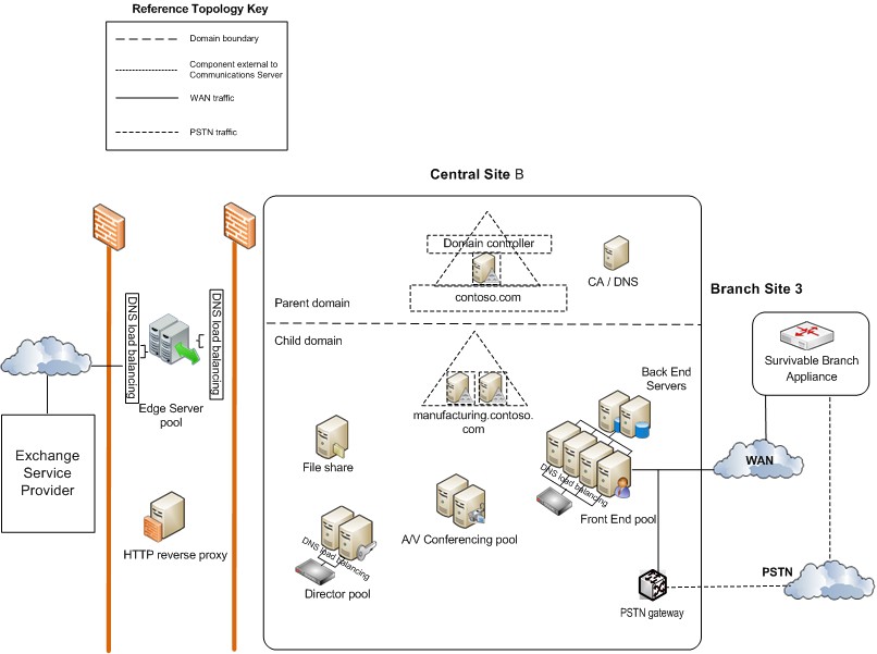

- Active Directory deployment. All
Microsoft Lync Server 2010 communications software deployments
reside in a single Active Directory forest. For this topology, the
customer has Lync Server deployed in two child domains,
retail.contoso.com and manufacturing.contoso.com.
- Accommodate more users by adding more Front End
Servers. The organization in this diagram has
five Front End Servers at Central Site A (for 40,000 users), and
four Front End Servers at Central Site B (for 30,000 users). If
either site needs to accommodate more users, you can simply add
Front End Servers to the pool at that site. The maximum number of
users per pool is 80,000, with eight Front End Servers.
However, each site can support even more users by adding another Front End pool to the site. To support these extra users, you need to add only one additional Front End pool (that is, just single pools at each site of A/V Conferencing Servers, Edge Servers, and Directors are sufficient, although more servers may need to be added to these pools).
- Using Standard Edition server at a branch
site. Aside from its use in Lync Server, this
organization considers Site C as a branch site because it has only
600 employees. However, the users there have many A/V conferences
among themselves. If it was deployed in Lync Server as a branch
site, the media for these conferences would run across the wide
area network (WAN) to and from a central site with A/V Conferencing
Server installed. To avoid this potential performance problem, they
have installed a Standard Edition server at this site, which will
host these conferences. And because a Standard Edition server is
installed there, Lync Server by definition considers it a central
site, and it is treated as such in Topology Builder and the
Planning Tool.
As long as the users at this site have a pool in another site set as their backup Registrar pool, they will have high availability for Enterprise Voice—voice support will fail over to the backup Registrar site automatically. For a more complete high availability solution at this site, you could deploy a second Standard Edition server there.
Although Site C is considered a central site, you do not have to deploy Edge Servers there. In this example, Site C will use the Edge Servers deployed at Site A.
- Monitoring Server and Archiving Server
collocation. This organization deploys both
Monitoring Server and Archiving Server. For organizations that
deploy both, we recommend that you collocate them to save server
investment. When collocated, Monitoring Server and Archiving Server
can each support up to 100,000 users.
Note that you need to deploy Monitoring Server and Archiving Server in only one central site. If the link between the two central sites goes down, the Message Queuing (also known as MSMQ) technology used by both Monitoring Server and Archiving Server helps preserve data while the link is temporarily down.
In this topology, Monitoring Server and Archiving Server use a separate database server than any Front End pool.. Topologies in which the Monitoring Server and Archiving Server share the same database servers as the Front End pool are also supported, although on large deployments such as this, separate database servers are recommended for performance.
- Branch site deployment options. The
organization in this topology has Enterprise Voice deployed as
their voice solution. Branch Sites 1 and 3 do not have a resilient
WAN link to the central site, so they have Survivable Branch
Appliances deployed to provide telephone service in case the WAN
link to the central site goes down. Branch Site 2 however has a
resilient WAN link, so you need only a public switched telephone
network (PSTN) gateway. The PSTN gateway deployed there supports
media bypass, so no Mediation Server is needed at Branch Site B.
For details about deciding what to install at a branch site, see
Planning for
Enterprise Voice Resiliency in the Planning documentation.
- SIP trunking and Mediation
Server. Notice that at Site A, Mediation
Server is not collocated with the Front End Servers. This is
because stand-alone Mediation Server is recommended for sites that
use SIP trunking. In most other instances, we recommend you
collocate Mediation Server with Front End Server. For details about
Mediation Server topologies, see Components and
Topologies for Mediation Server in the Planning
documentation.
- DNS load balancing. The Front End pool,
Edge Server pool, and the Director pool have DNS load balancing for
SIP traffic deployed. This eliminates the need for hardware load
balancers for the internal interface of the Edge Servers, and
significantly decreases the amount of time you have to spend on the
setup and maintenance of the hardware load balancers for the other
pools, as the hardware load balancers are needed only for HTTP
traffic. For details about DNS load balancing, see DNS Load Balancing
in the Planning documentation.
- Exchange UM deployment. Lync Server 2010
works with both on-premises deployments of Exchange Unified
Messaging (UM) and hosted Exchange UM. Central Site A
includes an Exchange Unified Messaging (UM) Server, which runs
Microsoft Exchange Server, not Lync Server. The Exchange UM
functionality for Lync Server runs on the Front End pool.
Central Site B uses hosted Exchange, so the Exchange UM Server functionality is also hosted.
For details about Exchange UM, see On-Premises Exchange Unified Messaging Integration and Hosted Exchange Unified Messaging Integration in the Planning documentation.