Applies to: Exchange Server 2010 SP3, Exchange Server 2010 SP2
Topic Last Modified: 2010-11-11
When designing a highly available solution for Mailbox servers, you need to ensure high availability for a variety of infrastructure components, including:
- Infrastructure services, such as Active Directory and Domain
Name System (DNS)
- Database availability group (DAG) member servers
- Individual storage components, such as disks, storage
controllers, and storage shelves
- Individual network components, such as routers, switches, and
aggregators
- Server and storage racks
- Power buses
- Datacenters
Each of these component areas represents potential points of failure, which are sometimes referred to as failure domains. As a result, the availability level of your DAG ultimately depends on how you design the solution to isolate and minimize the negative effects that a failure in one of these domains can have on your DAG environment. To achieve independence between failure domains, each failure domain must have one copy of the database. In addition, because a failure would result in multiple copies being unavailable, no more than one copy is required per failure domain.
For example, consider a scenario in which you have two copies of a database. Each copy is stored on a separate set of disks but both are located within the same storage array. If the storage array fails or becomes unavailable for any reason, both copies would be unavailable. In this example, the failure domain is the storage array. Only a single copy of each mailbox database should reside on the array. Otherwise, if the array fails, multiple (perhaps all) copies of the database will be unavailable.
When planning your mailbox architecture, consider the following additional design points:
- Will you deploy multiple database copies?
- How many database copies will you deploy?
- Will you have a site-resilient architecture?
- What kind of Mailbox server resiliency model will you
deploy?
- How many Mailbox servers will you deploy?
- What backup model will you utilize?
- What storage architecture will you utilize?
For detailed information about how to plan for these questions, see Understanding High Availability Factors.
Contents
Unbalanced Database Copy Layouts
Designing a Balanced Database Copy Layout
Active Database Distribution in Example Scenario During Server Failures
Looking for management tasks related to high availability and site resilience? See Managing High Availability and Site Resilience.
Unbalanced Database Copy Layouts
To understand how the database copies should be distributed within a DAG, consider a DAG design that Contoso, Ltd is planning for their highly available Mailbox server solution. Contoso is building a DAG comprised of:
- 4 Mailbox servers
- 20 mailbox databases
- 2 copies of each mailbox database
All servers are deployed in a single datacenter, each server has its own dedicated storage, and each server is deployed in its own server rack.
Contoso requires that two highly available database copies (for example, non-lagged) be available at all times, and that the solution survive two simultaneous DAG member outages without negatively affecting the availability of the databases.
Based on these requirements, the database copy layout used is shown in the following figure.
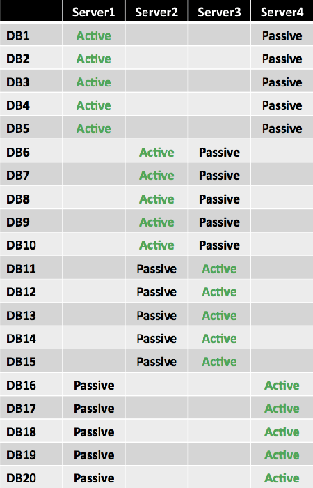
Initially, the design looks sound because it spreads the active copies of each database across the four DAG members. However, there are concerns with this design. The layout isn't optimal from a server resource perspective. For example, when a single server fails, it results in an uneven distribution of databases, as shown in the following figure.
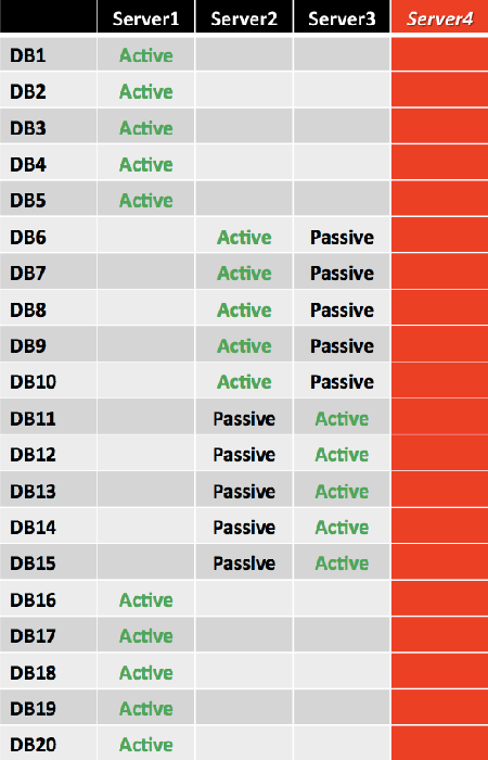
The failure of Server4 results in databases DB16 through DB20 being activated on Server1, instead of being distributed across the remaining three servers. The result is an uneven distribution of activated mailbox databases and an uneven utilization of server resources. Compared to the other two remaining servers (Server2 and Server3), the utilization of Server1 doubled.
Another concern is the DAG doesn't contain enough copies to survive two simultaneous server outages in all cases. Another server failure could result in 50 percent of the databases being unavailable. If Server1 and Server4 fail or become unavailable within moments of each other, 10 databases would be unavailable, as shown in the following figure.
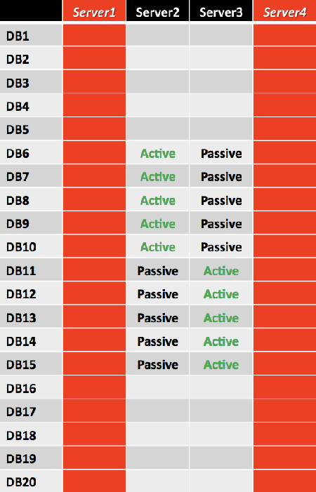
This design doesn't meet the core requirement of being able to survive a double server failure. To survive a double server failure and maintain all active databases, a third copy must be deployed, and a new layout must be devised.
Designing a Balanced Database Copy Layout
Designing a balanced database copy layout may require you to revisit several design decisions to derive the optimal design. Use the following design principles when planning the database copy layout:
- Make sure that you minimize multiple database copy failures of
a mailbox database by isolating each copy from one another and
placing them in different failure domains. For example, don't place
more than a single database copy of a specific mailbox database
within the same server rack or in the same storage array.
- Lay out the database copies in a consistent, distributed
fashion to make sure that the active mailbox databases are evenly
distributed after a failure. The sum of the activation preferences
of each database copy on any specific server must be equal or close
to equal. This results in an approximately equal distribution after
failure, assuming replication is healthy and up to date.
Building Blocks
To adhere to the previous design principles, we recommend placing the database copies in a particular arrangement that ensures all active copies are symmetrically distributed across as many servers as possible. The arrangement of database copies is based on a building block concept.
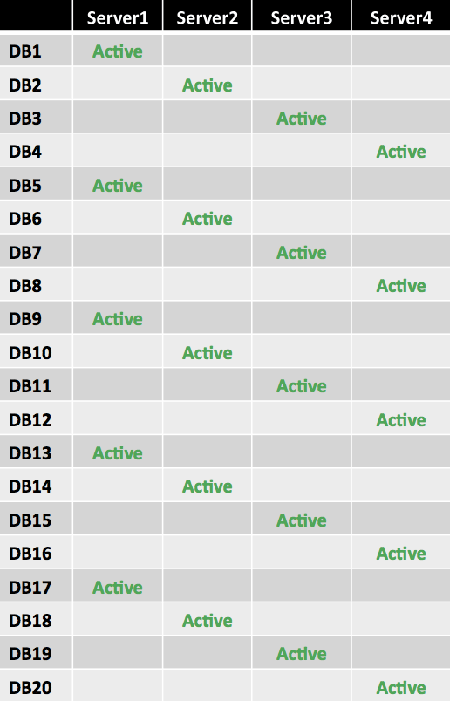
The first building block (known as the level 1 building block) is based on the number of Mailbox servers that will host active database copies. Assume this number is N. N defines not only the number of Mailbox servers, but also the number of databases within the building block. One active database copy is distributed on each server, forming a diagonal pattern. As in the previous example, there are 4 Mailbox servers and 20 mailbox databases. The size of the first level 1 building block is 4, as shown in the following figure.

The same pattern is repeated for each remaining level 1 building block set. Because there are 20 databases, there are five level 1 building block sets, as shown in the following figure.
When you add a second database copy, you place it differently for each building block set. Because one server already hosts the active copy, there are N – 1 servers available to host the second database copy. As you use each of these N – 1 servers once, you have a complete symmetric distribution that forms the new larger building block. Therefore, the new building block (known as the level 2 building block) size becomes N × (N – 1) databases. This means that the second database copy for the first database is placed on the second server, and each second copy thereafter is deployed in a diagonal pattern within the building block. After the pattern is completed within the first level 1 building block set, the starting position of the second copy for the next block is offset by one so the second copy starts on the third server.
In the example, the building block size now becomes 4 × (4 – 1) = 4 × 3 = 12, which means that 12 databases make up each level 2 building block set. For the level 1 building block set 1 (DB1 through DB4), the second copy for DB1 is placed on Server2, while for the level 1 building block set 2 (DB5 through DB8), the second copy for DB5 is placed on Server3. The placement of the starting server for each level 1 building block set is offset from the previous level 1 building block set by one server. This layout is continued by placing the second copy of DB9 on Server4. This ensures that a Server1 failure activates second copies across all three remaining servers rather than activating multiple databases on the same server.
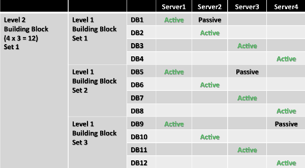
This pattern is repeated for each remaining second building block set. Because there are 20 databases, there are two level 2 building block sets in this example. Note that the second copy for DB13 is placed on Server2.
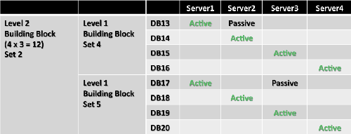
To understand this logic better, compare database copy placement for DB1, DB5, and DB9. These databases each have an active copy hosted on Server1. If Server1 fails, you want to have second database copies activated on different remaining servers to achieve equal load distribution. You can achieve this by placing a second database copy of DB1 on Server2, a second database copy of DB5 on Server3, and a second database copy of DB9 on Server4. Starting with DB13, you simply repeat the pattern. The remaining database copies are added in a diagonal pattern, as shown in the following figure.
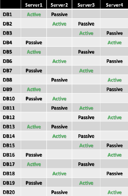
Note that the second building block (DB13 through DB20) contains only 8 databases, not 12. As a result, this design won't be entirely symmetrical if a single failure occurs. To provide a fully symmetric distribution, plan your architecture so the number of databases is a multiple of the largest building block size. (In this example, optimal numbers are 24, 36, 48, or 60 databases, and so on.)
As you add a third database copy, again you must place it differently for each group of now N × (N – 1) databases. Because you now have only N – 2 servers available from which to select for the third database copy placement, this generates N – 2 variations. The new building block (known as the level 3 building block) becomes N × (N – 1) × (N – 2) databases. Therefore, the third database copy for the first database is placed on the third server, and each third copy thereafter is deployed in a diagonal pattern according to the starting position within this new building block. After the pattern is completed within the first level 1 building block set, the starting position is offset by one so that the third copy is placed in the fourth position.
In this example, the building block now becomes 4 × (4 – 1) × (4 – 2) = 4 × 3 × 2 = 24, which means that 24 databases make up each level 3 building block set. To produce the symmetric database placement pattern, place the third database copy of DB1 on Server3 (which is the first available server because Server1 hosts the first copy and Server2 hosts the second copy), and offset each additional copy by one until you reach the end of the level 1 building block set 1. For the next building block set, again place the third database copy on the next available server (Server4) and continue in the same manner until you reach DB12, which marks the end of the level 2 building block set 1. For DB13 through DB20, follow the same pattern but offset the third database copy placement by one so it doesn’t end up on the same servers as DB1 through DB12.
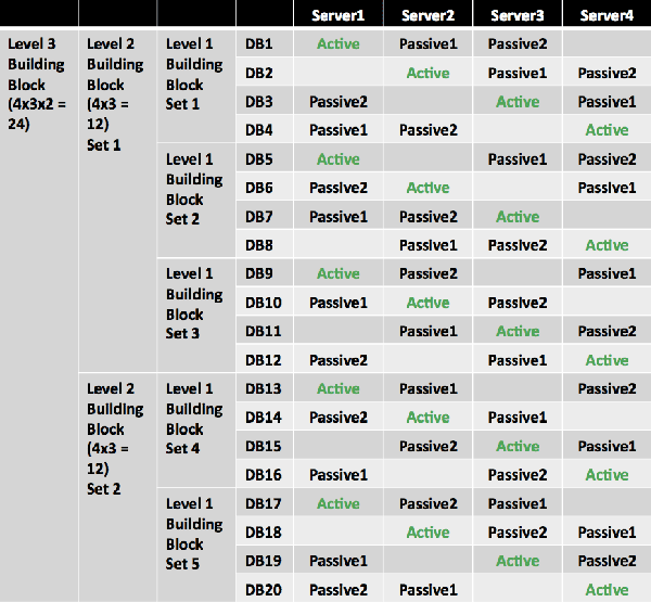
Again, to understand this logic better, compare database copy placement for databases DB1 through DB13. These databases have the active database copy hosted on Server1, and the second database copy hosted on Server2. If these servers fail, you want to have the third database copies activated on different remaining servers to achieve equal load distribution. You can achieve this by placing the third database copy of DB1 on Server3 and the third database copy of DB13 on Server4. Similar pairs are formed by DB2 and DB14, DB3 and DB15, and so on. Starting with DB25, you simply repeat the pattern (this example doesn't address that many databases).
Note that the third building block (DB1 through DB20) contains only 20 databases, not 24 databases. As a result, this design won't be entirely symmetrical if double failures occur. Again, to provide a fully symmetric distribution, plan your architecture so the number of databases is a multiple of the largest building block size. (In this example, the optimal numbers are 24, 48, or 72 databases, and so on.)
As you add a fourth database copy, again you must place it differently for each group of now N × (N – 1) × (N – 2) databases. The new building block becomes N × (N – 1) × (N – 2) × (N – 3) databases. This follows the same logical approach and ensures that the database distribution is even within the new building block in case three servers fail.
The example of four servers leaves only one variation for placing the fourth database copy (only one remaining server is available). Therefore, the building block size actually remains at 24. This is also apparent when using the formula for building block size: 4 × 3 × 2 × (4 – 3) = 4 × 3 × 2 × 1 = 24.
As you continue to add more database copies, the building block keeps growing such that the general formula for the building block size is Perm(N,M) = N × (N – 1) … (N – M + 1) = N!/(N – M)! = C(N,M), where N = number of servers and M = number of database copies. This becomes obvious as you realize that complete symmetric distribution of the database copies is achieved by selecting all possible permutations of M database copies across N available servers.
There are several caveats to using this methodology:
- Deploying a number of databases that isn't a multiple of the
largest building block size results in a nonsymmetrical
distribution of active databases during failure events.
- Deploying architectures to mitigate multiple domain failures
may result in a nonsymmetrical distribution of active databases
during failure events. This is because failure domain definitions
impose restraints on database copy placement, which breaks the
symmetry of the pattern.
- Deploying site-resilient solutions that result in out-of-site
database *over events may result in a nonsymmetrical distribution
of databases activated in the secondary datacenter during primary
datacenter server failure events.
Active Database Distribution in Example Scenario During Server Failures
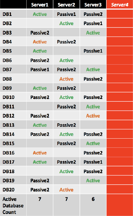
Using the previous example, in the event of a single server failure (for example, a failure of Server4), the active mailbox databases are distributed as shown in the following figure. The second copy is activated for DB4, DB8, DB12, DB16, and DB20, denoted as Active in orange.
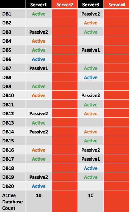
If double server failure occurs (the third copy is activated for several databases and denoted as Active in green), the remaining two servers, Server1 and Server3, will have an equal number of activated mailbox databases.
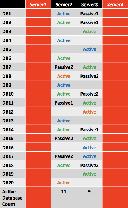
However, because the number of databases in this example isn't a multiple of the largest building block size (24 databases), not all double server failure events will result in a symmetrical distribution.
Design Scenarios
To understand the design principle of the database copy layout, including the associated mathematical formula, consider two other architectural layouts.
Design Scenario: Active/Passive User Distribution Site-Resilient Solution
In this scenario, Contoso decides to deploy the following architecture:
- The DAG is extended across two datacenters, operating in an
active/passive user distribution model.
- Each server is deployed in a separate server rack.
- Each server's storage is isolated from the other servers'
storage within the datacenter.
- There are four Mailbox servers per datacenter.
- There are a total of 24 mailbox databases.
- The desire is to have four highly available database copies and
to survive a double server failure or a single datacenter
failure.
In this example, the level 1 building block is 4, the databases are grouped into units of four, and the active copies are distributed across the four servers within the building block.
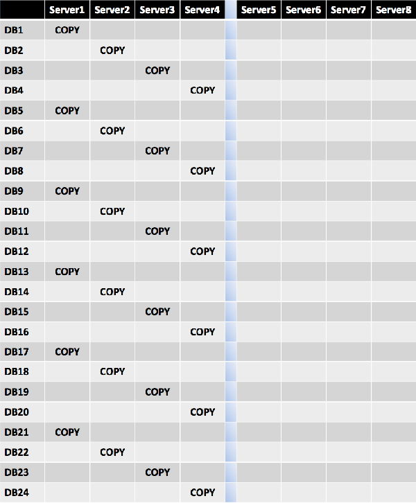
For each server hosting active copies, the second database copy is distributed as evenly as possible across all remaining member servers, continuing with a diagonal pattern because each copy is isolated from one another. In this example, the level 2 building block becomes 12, which becomes the repeating set every 12 databases.
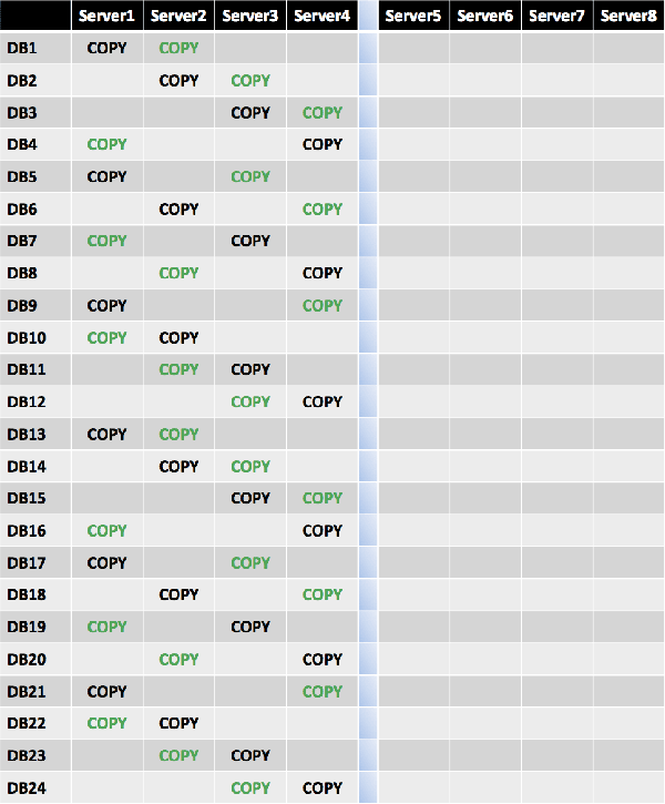
Because this site resilient solution is for an active/passive user distribution model with an equal number of servers and database copies in both datacenters, the third database copy is placed in a diagonal pattern across Server5 and Server6, using the level 1 building block value of 4. This ensures that Server5 and Server6 mirror the first database copy placement on Server1 through Server4.
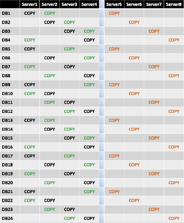
Because this site resilient solution is for an active/passive user distribution model with an equal number of servers and database copies in both datacenters, the fourth database copy is placed in a diagonal pattern across Server5 and Server6, using the level 2 building block value of 12. This ensures that Server5 and Server6 mirror the second database copy placement on Server1 through Server4.
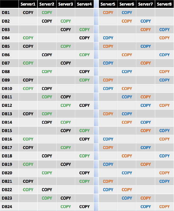
If a single server failure occurs, the remaining three servers in the primary datacenter will have an equal number of activated mailbox databases (8 per server).
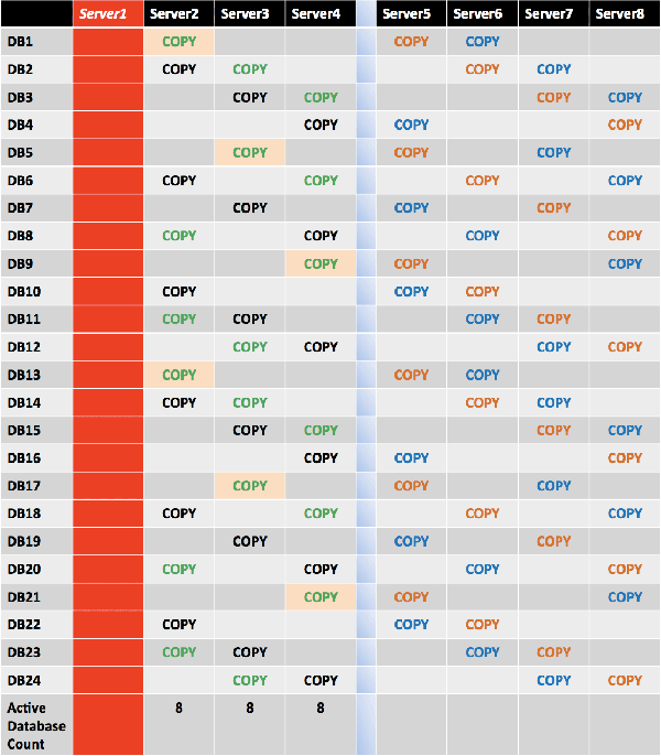
If two simultaneous server failures occur, the remaining two servers in the primary datacenter will have an equal number of activated mailbox databases (10 per server), while 4 databases will be activated in the secondary datacenter.

Design Scenario: Multiple Failure Domains
In this example, Wingtip Toys decides to deploy the following architecture:
- All servers are deployed in a single datacenter.
- Servers are grouped in units of two.
- Each of the two servers is placed in the same rack with its
storage.
- There are a total of 3 racks and 6 servers.
- There are a total of 18 mailbox databases.
- The desire is to have three highly available database copies
and to survive two member server failures or one rack failure.
In this example, the level 1 building block is 6, so the databases are grouped into units of 6, and the active copies are distributed across the six servers within the building block.

For each server hosting active copies, the second database copy is spread as evenly as possible across all remaining member servers, while also ensuring that two copies of the same database aren't placed in the same server rack. In this example, instead of the level 2 building block formula of N × (N – 1), the formula of N × (N – 2) is used to ensure two copies of the same database aren't placed in the same rack. This means that the level 2 building block is 6 × 4 = 24.
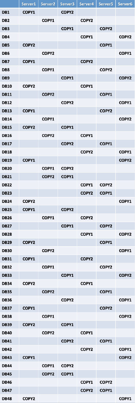
The third database copy is placed in a diagonal pattern across the servers, again ensuring that multiple copies of the same database aren't placed in the same server rack. In this example, instead of the level 3 building block formula N × (N – 2), the formula of N × (N – 2) × (N – 4) is used to ensure two copies of the same database aren't placed in the same rack. This means that the level 3 building block is 6 × 4 × 2 = 48.

If a single server failure occurs, the remaining five servers in the primary datacenter will have a near equal number of activated mailbox databases. Four servers will have 10 activated databases per server, while one server (the rack partner) will have 8 activated databases.

If two simultaneous server failures occur (different racks), the remaining four servers will have a near equal number of activated mailbox databases.

If two simultaneous server failures occur (same rack), the remaining four servers will have an equal number of activated mailbox databases.


