

Topic Last Modified: 2011-04-11
The following figure shows the topology that was used to test the metropolitan site resiliency solution. The topology shown in has been created from "off the shelf" Microsoft products combined with third-party hardware and software. The solution does not require specific products from any particular vendor, so long as those products meet the prerequisites and requirements set forth in this section and supporting Microsoft product documentation. Depending on the mix of components you choose for your particular implementation of this solution, you might need help from your vendor of choice to deploy this solution.
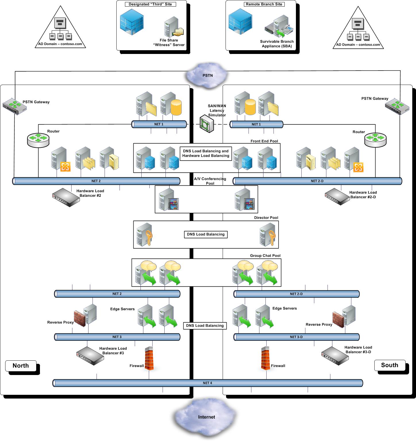
This figure is representative of the topology tested, but for purposes of clarity, it does not necessarily depict the number of servers used in each pool in the actual test topology. For example, in the actual test topology there were four Front End Servers in each site.
As shown in the figure, the tested topology deployed two central sites and a branch office, along with a third location that hosted a file server functioning as a Windows Server 2008 R2 Failover Clustering Service file share witness. For details about using a witness in a failover cluster, see http://go.microsoft.com/fwlink/?LinkId=211004.The file share witness is available to all Windows Server 2008 R2 Failover Cluster nodes in both central sites. All Windows Server 2008 R2 Failover Clusters used in this solution use the Node and File Share Majority quorum mode.
The following topics discuss each of the solution components shown in preceding figure.
