Topic Last Modified: 2011-02-01
The majority of the work that a designer will do in the Lync Server 2010, Planning Tool will be defining the entries for the IP addresses and fully qualified domain names (FQDNs) for the entries on the network diagram. The information that is entered on this page carries over into the reports and other information contained in the Planning Tool. Additionally, the information is also part of the exported topology that is then imported by Topology Builder, which is used to publish the infrastructure configuration.
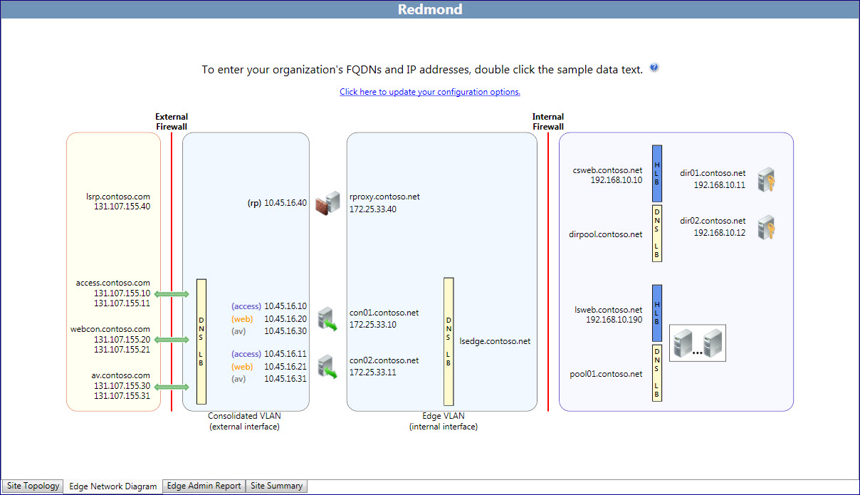
The Planning Tool creates a network diagram with default text for IP addresses and FQDNs. The default information is not exported to a Topology Builder export file. If you use the Planning Tool to edit the network diagram information, the information entered will be exported into a Topology Builder document, and then can be imported into Topology Builder.
 Important: Important: |
|---|
| Servers that are selected in the interview portion of the Planning Tool will be exported, but the default IP addresses and the FQDNs will not. |
To edit the network diagram and input values:
- Choose a section of the network to begin working on. For this
example, work from the external network (at left) to the internal
network.
- Double-click the text, rp01.contoso.net. In the dialog
box that opens, type the actual FQDN of the server rp01.contoso.net
and the actual IP address, replacing the 131.107.155.1.
- Click OK to save the entries.
 Note:
Note:When an entry is successfully edited and saved, the text will change from red italic to black, non-italic text. - Continue to edit IP addresses and FQDNs, providing virtual IP
addresses for hardware load balancers or server entries for Domain
Name System (DNS) load balancing for servers in pools.
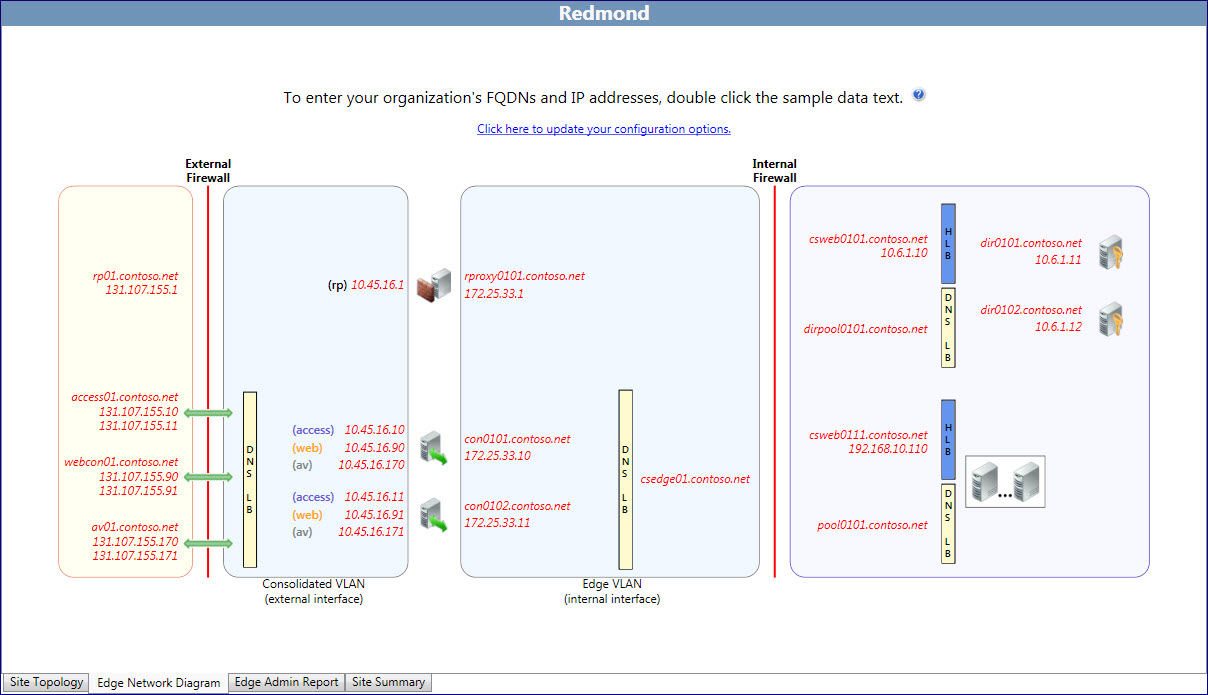
In the example diagram, access01.contoso.net, webcon01.contoso.net, and av01.contoso.net are edited. The actual IP addresses of the external interfaces are entered for the DNS load balancing associated with the servers and the external FQDN.
The external interfaces of the Edge Servers are edited to their actual production names and IP addresses. The reverse proxy external IP address is set. The Edge Server and reverse proxy internal IP addresses and FQDNs are entered.
The process of updating the default values to the assigned production values continues until all servers have been edited and updated with their permanent values.
A helpful feature of the Planning Tool is that it can incrementally assign a range of IP addresses and server host names, rather than requiring the designer to edit each separate server in a pool. For example:
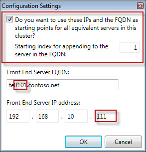
- Double-click the pooled Front End Servers. When the dialog box
opens, select Do you want to use the IPs and FQDN as starting
points for all equivalent servers in this cluster?. Set the
index value by typing the increment, which by default is one, in
the Starting index for appending to the server in the FQDN
box.
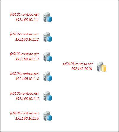
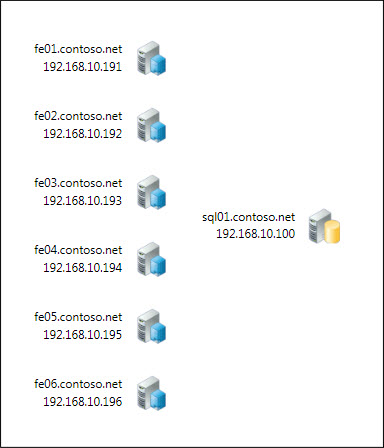
- In the example, the starting value for the first server is
fe0101.contoso.net and an IP address of 192.168.10.111.
- Select the increment, and then set the index value to 1.
- Type fe0.contoso.net in Front End Server FQDN,
type 192.168.10.191 in Front End Server IP address,
and then click OK.
- The auto-increment feature updates all servers in the pool to
fe01 through fe06, and all IP address from 192.168.10.191 to
196.
After you have completed all edits, you save the topology. To do this, you do the following:
To save the Planning Tool design, click File, and then click Save Topology or Save Topology As. If a Save Planning Tool As dialog box appears, type a name for the file in File name, and then click Save.
The completed network diagram would look similar to the screen shot of the edited network. All entries have been edited to depict the design’s production IP addresses and FQDNs. This diagram represents the outcome of editing the initial diagram with red, italic text, as depicted with the starting network diagram.
| Note: |
|---|
| We recommend, although it is not required, that all network information be edited before exporting the topology. Editing the topology in the Planning Tool will provide for a more complete set of configuration documents that will lead the deployment team through the deployment phases and serve as references for the operations team during production deployment. |