

Topic Last Modified: 2010-05-08
Planning for CAC requires that you fully understand your enterprise network topology before you begin defining policies. Follow these steps to help plan your call admission control policies.
- Identify the hubs/backbones (called network regions) within
your enterprise network.
- Identify the offices or locations (called network sites) within
each network region.
- Identify the IP subnets assigned to each network site.
- Determine the preferred network route between every pair of
network regions.
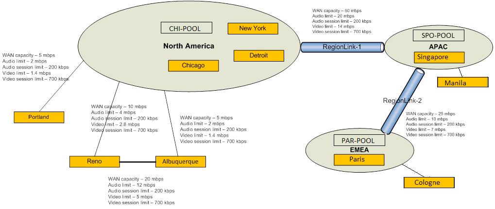
To explain these concepts, we’ll use the example network topology shown in the following figure.
 Identifying Network Regions
A network region represents a network backbone, a group of network hubs with similar bandwidth or a single network hub. Network backbones and hubs have high bandwidth capacity. This typically spans a much wider geographic area than a network site. Our example topology has three network regions: North America, EMEA, APAC.
A network region comprises one or more network sites. Consider a network region an arbitrary boundary where you want to enforce CAC policies. Work with your network operations team to decide how to partition your enterprise topology into network regions.
Identifying Network Sites
A network site represents a branch office location, a set of buildings or a campus. Network sites represent collections of subnets with similar bandwidth. Start by inventorying all of your enterprise offices. If they share the same network bandwidth, group them together to simplify the number of network sites to manage. Policies are assigned to network sites to enable CAC and Enhanced 9-1-1. In our example topology, the North America network region consists of three network sites: New York, Chicago, and Detroit.
Network sites further refine bandwidth limitations within a region. Where a subset of a region has different bandwidth than the rest of the region, defining this subset as a network site provides the ability to apply different CAC policies to that site. You configure CAC by associating network sites with network regions, and then creating bandwidth-limiting policies to apply to the bandwidth-constrained WANs that connect the sites and regions.
After you have determined the maximum bandwidth capacity of the network connection to each site (referred to as a network link), decide how much bandwidth (CAC policy) to allocate for voice and video calls. CAC policies can be created to define the following limits:
- Maximum total bandwidth to allocate for audio
- Maximum total bandwidth to allocate for video
- Maximum bandwidth that can be allocated for a single audio call
(session)
- Maximum bandwidth that can be allocated for a single video call
(session)
To optimize bandwidth utilization on a per session basis, it’s important to consider the type of audio and video codecs used. It is important to avoid under-allocating sufficient bandwidth for a codec. Conversely, if you want to limit media from using a codec that requires more bandwidth, you don’t want to over-allocate the bandwidth by setting the maximum bandwidth per session too high. Use the following table to help optimize the maximum per session bandwidth settings.
Bandwidth utilization by codecs
| Codec | Typical bandwidth usage | Upper bandwidth limit with no forward error correction (FEC) | Upper bandwidth limit with forward error correction (FEC) |
|---|---|---|---|
|
RTAudio (8khz) |
25.9 kbps |
39.8 kbps |
51.6 kbps |
|
RTAudio (16khz) |
34.8 kbps |
57 kbps |
86 kbps |
|
Siren |
22 kbps |
51.6 kbps |
67.6 kbps |
|
G.711 |
59.8 kbps |
92 kbps |
156 kbps |
|
G.722 |
42.8 kbps |
99.6 kbps |
163.6 kbps |
|
RTVideo (CIF 15 fps) |
203 kbps |
250 kbps |
N/A |
|
RTVideo (VGA 30 fps) |
492 kbps |
600 kbps |
N/A |
You will use this information when you run Communications Server Management Shell cmdlets to configure your CAC policies.
Identify IP Subnets
For each network site, you will need to work with your network administrator to determine what IP subnets are assigned to each site. If your network administrator has already organized the IP subsets into regions and sites, then your work is significantly simplified.
In our example, the New York site in the North America region is assigned the following IP subnets: 172.29.80.0/23, 157.57.216.0/25, 172.29.91.0/23, 172.29.81.0/24. Suppose Bob, who normally works in Detroit, travels to the New York office for training. When he turns on his computer and connects to the network, his computer will get an IP address in one of the four ranges, 172.29.80.103.
Identify Network Links
Network links represent the physical WAN connections between regions and sites. In our example topology, there are two regional network links, five network links between regions and sites, and one network link between two sites.
The two regional links are between North America and APAC, represented as link 1, and between APAC and EMEA, represented as link 2.
The site links are indicated by the lines connecting Portland, Reno, and Albuquerque to the North America region as well as Manila to the APAC region, and Cologne to the EMEA region. The line between Reno and Albuquerque shows a direct network link between these two sites.